This project is about building a system to translate a hand sketched human face into a 3D face model. The main problem about this system is Building a model to learn the outline pattern of human face and applying GAN to the generated face more real.
We have tried two methods in this project. One is a two step model, generating the RGB face and 3D face in two steps. The other is an End-to-End Pix2RGBD model, which tries to combine the two models together and generate 3D model directly from the hand skecthed image.
The Two Step Model is a concatenation of two models. They are Pix2Pix Model and 3D Generation Model.
This model was published in [1], which aims to translate an image into another image. In this project, we take advantage of this model to translate our hand sketched human face into a colored RGB human face.
We apply a similar network structure descibled in [1], but we have changed some hyper parameters to make this model more suitable for our system. The GAN is applied in this model. The structure of generator part is shown below.
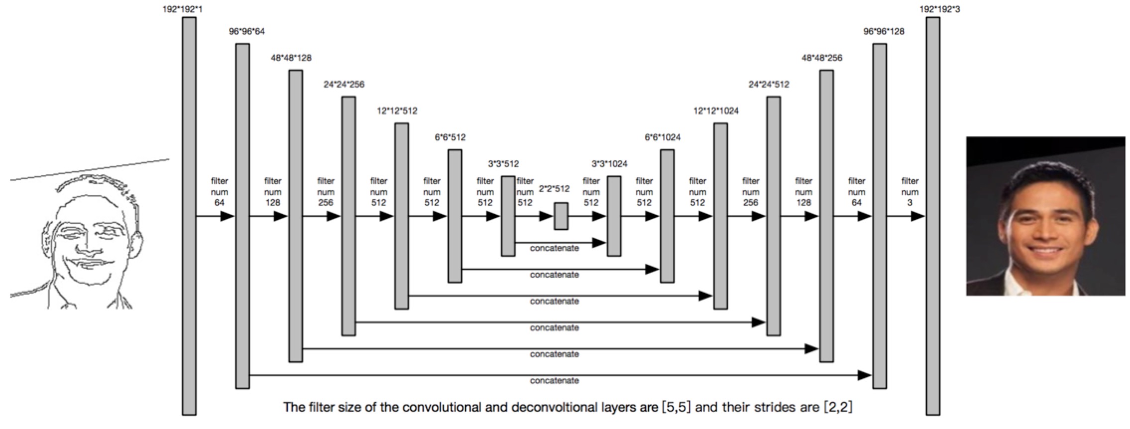
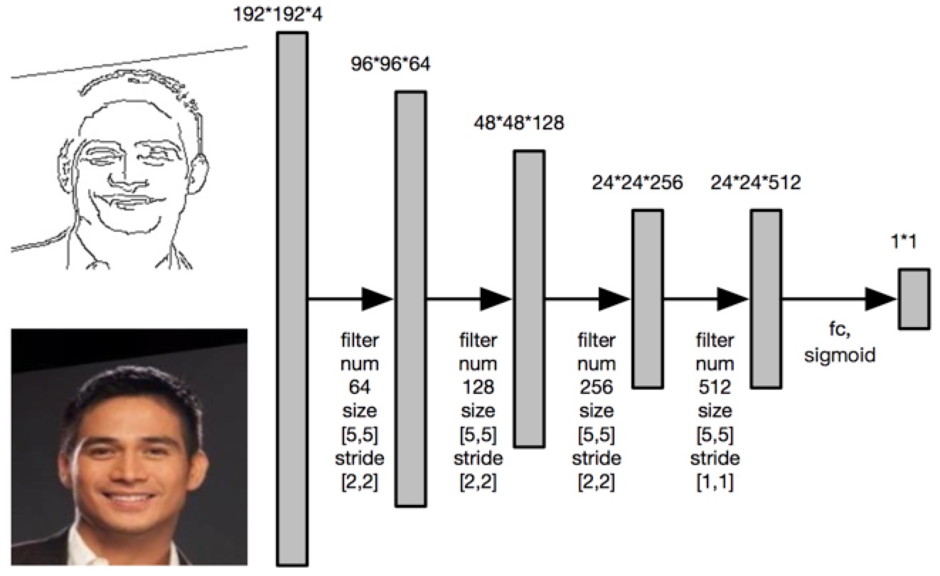
The input is an image with size 192*192, which only contains two kind of values (0, 255). The generator will generate a 192*192 colored image with three channels. The structure of the discriminator is shown below. The 192*192*4 input tensor is a concatenation of a hand skectched image and its corresponding RGB image. The discriminator will decide whether the RGB image is real or fake.
The loss function of our model is
$$L_{GAN}=\mathbb{E}_{y\sim p_{data}(y)}[\log D(y)]+\mathbb{E}_{x\sim p_{data}(x),z\sim p_{z}(z)}[1 - \log D(G(x))]\\
L= arg~\underset{G}{min}~\underset{D}{max}~L_{GAN} +\lambda \mathbb{E} \left \| y-G(x)) \right \|_1$$
x is the input hand sketched image; y is the ground truth; D and G are the generator and discriminator.
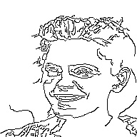
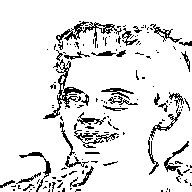
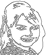
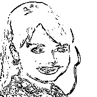
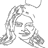
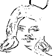
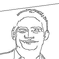
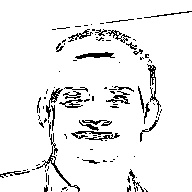
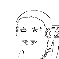
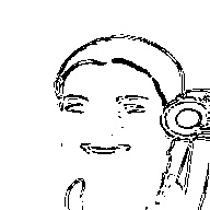
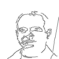
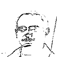
In this project, we use the data from CelebA[3]. It contains 202,599 aligned face images. Since limited calculation resources, we only select the first 10,000 images. Buy applying the Canny and Sobel edge detection algorithm to generate the sketched images. So we can have a dataset with 20,000 pairs of training images. Here are some samples from our dataset.
Image | Canny | Sobel | Image | Canny | Sobel |
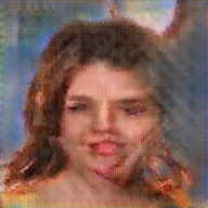
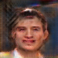
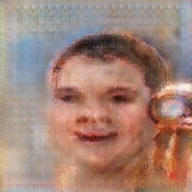
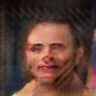
---|---|---|---|---|---|
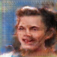
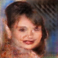
The table below illustrate some of the generated RGB face and it ground truth.
Sketch | Ground Truth | Generated Face | Sketch | Ground Truth | Generated Face |
---|---|---|---|---|---|
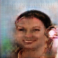
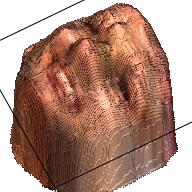
The 3D Generation Model aims to translate the colored face image into a 3D model. Here, we use the idea from [2]. In [2], the author rasied a Volume Regression Network (VRN) to generate a 192*192*200 volume to demonstrate the outline of a human face.
From the name of this network (Volume Regression Network), we can simply guess the loss function should be cross-entropy. The loss function of this network is
$$L=\sum_{w,h,d}[V_{whd}\log \widehat{V_{whd}}+(1-V_{whd})\log (1-\widehat{V_{whd}})]$$
Here $V_{whd}$ is the output of the VRN, $\widehat{V_{whd}}$ is the ground truth. We can find that the VRN is quite straightforward method to get the 3D mesh of a human face.
The VRN is much more complicated than the Pix2Pix model, so we can not draw all the details here. Similar to the Pix2Pix Network, the VRN also applies some skip architecture to maintain the information from previous layers. The VRN contains two hourglass network [5]. The image below illustrate the structure of the VRN.
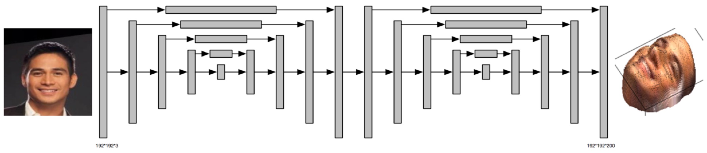
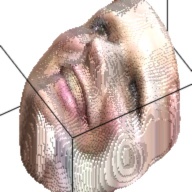
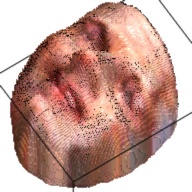
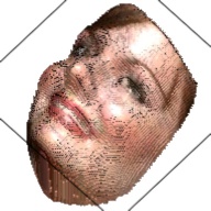
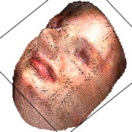
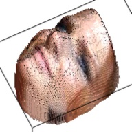
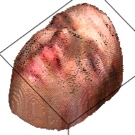
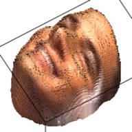
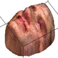
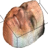
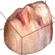
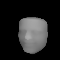
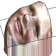
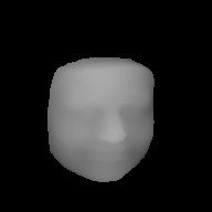
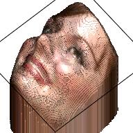
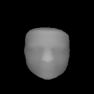
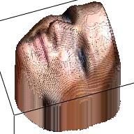
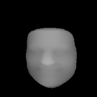
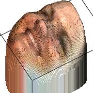
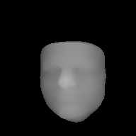
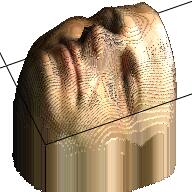
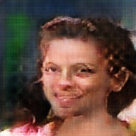
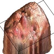
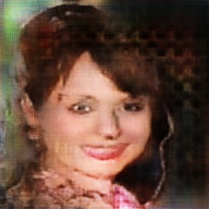
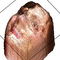
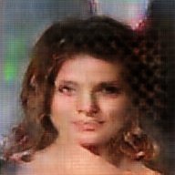
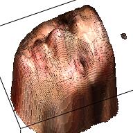
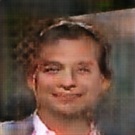
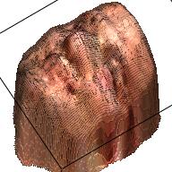
The output of this network is a 192*192*200 tensor, which is extremely sparse and we only take advantages of the elements larger than 1. These elements form a outline of the human face. By setting this elements as the corresponding RGB value from the RGB image, we can visualize the final 3D model. This are some examples about the 3D model generated from the RGB images.
Sketch | RGB Ground Truth | 3D Ground Truth | Generated RGB | Generated 3D |
---|---|---|---|---|
The image below demonstrate the work flow of this method.
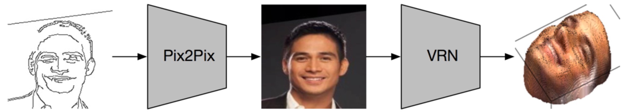
In this project we also try another method to do an end-to-end training, which takes advantages of the Pix2Pix Network to get the final 3D model in one network.
The output of the VRN is a 192*192*200 volume, which contains a great number of parameters. Just forcing the Pix2Pix Network to generate the 3D volume, we can not get a reasonable output.
By observing the 3D volume generated by VRN, we can find that a lot of elements are zero. To achieve a similar effect, we translate the 192*192*200 volume in to a 192*192 image with only one channel. We call it depth channel. Concatenate the depth channel with the RGB channel, we can generate a 192*192*4 RGBD image, which contains only a few parameters to learn.
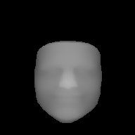
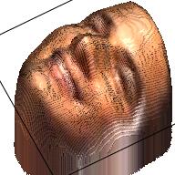
We apply the VRN on the images in our dataset and get 10,000 RGBD images. The table below displays some samples about the RGBD images. From the samples we can find that with only RGBD information, we can also revcover a reasonable human face, even though the 3D model might be a little weird.
RGB | Depth | RGBD | RGB | Depth | RGBD |
---|---|---|---|---|---|
We use a similar Pix2Pix Network structure here. The only difference is that the output is 192*192*4 with an extra channel denoting the depth. Here are some examples of the output.
Sketch | RGB Ground Truth | RGBD Ground Truth | Generated RGB | Generated RGBD |
---|---|---|---|---|
Notice that this model can also output a reasonable result. In some cases, it can even outperform the two steps method, with much less calculation, since the VRN is an extremely large network with millions of parameters.
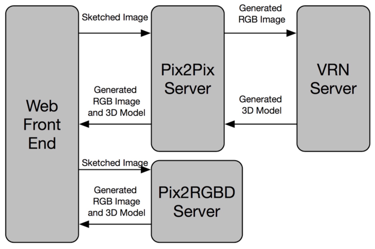
In this part, we will talk about the implementation of this system. This system contains four parts. Web front end, Pix2Pix Server, VRN Server and Pix2RGBD Server. Since loading the model into memory takes a long time, we encapsulate the two models as two individual service and load the model into memory. Only do the inference when there is a request.
In this part, we will have a whole view about the implemention of this project. The image below illustrate the module decomposition. The message between different modules are implemented by socket.
The web front end aims to handle the human interaction and display the RGB image and 3D model to the user. It will send the human sketched image to the Pix2Pix Sever and receive the generated RGB image and 3D model.
The Pix2Pix Server will translate the hand sketched image into a RGB image then it will send this image to the VRN Server and get the 3D model. Finally, it will send the generated RGB image and 3D model to the Web Front End.
The VRN Server aims to translate the RGB image, recevived from Pix2Pix Server, into a 3D model and send this 3D model to Pix2Pix Server.
The Pix2RGBD Server aims to translate the hand sketched image, recevived Web Front End, into a 3D model directly and send this 3D model to the Web Front End.
In this project, we successfully build a system to translate the human skteched human face into a 3D model. We have tried two different approaches, one is a combination of Pix2Pix and VRN, the other one is an Pix2RGBD model. It turns out the Pix2RGBD model can also output a resenable result with less calculation. We have also developped a web demo for this project.
[1] Isola, Phillip, et al. “Image-to-image translation with conditional adversarial networks.” CVPR. 2017.
[2] Jackson, Aaron S., et al. “Large Pose 3D Face Reconstruction from a Single Image via Direct Volumetric CNN Regression.” ICCV. 2017.
[3] Liu, Ziwei, et al. “Deep learning face attributes in the wild.” ICCV. 2015.
[4] Zhu, Xiangyu, et al. “Face alignment across large poses: A 3d solution.” CVPR. 2016.
[5] Newell, Alejandro, et al. “Stacked hourglass networks for human pose estimation.” ECCV. 2016.
We can use SMO (Sequential Minimal Optimization) to optimize this problem. Select $\alpha_a$ and $\alpha_b$ set $\alpha_ay_a+\alpha_by_b+\sum_{i\neq a,i\neq b}\alpha_i^*y_i = 0$, we can get $\alpha_ay_a+\alpha_by_b = \alpha_a^*y_a+\alpha_b^*y_b = -\sum_{i\neq a,~ i\neq b}\alpha_i^*y_i = -\sum_{i\neq a,~ i\neq b}\alpha_iy_i=M$, here $\alpha_i^*$ is the value of $\alpha_i$ before optimalization.
$$L=\alpha_a+\alpha_b-\alpha_ay_ax_a\sum_{i\neq a,i\neq b}\alpha_iy_ix_i-\alpha_by_bx_b\sum_{i\neq a,i\neq b}\alpha_iy_ix_i-\alpha_ay_ax_a\alpha_by_bx_b\\
-\frac{1}{2}\alpha_a^2x_ax_a-\frac{1}{2}\alpha_b^2x_bx_b+const\\
=y_a(M-\alpha_by_b)+\alpha_b-(M-\alpha_by_b)x_a\sum_{i\neq a,i\neq b}\alpha_iy_ix_i-\alpha_by_bx_b\sum_{i\neq a,i\neq b}\alpha_iy_ix_i\\
-\alpha_b(M-\alpha_by_b)y_bx_ax_b-\frac{1}{2}(M-\alpha_by_b)^2x_ax_a-\frac{1}{2}\alpha_b^2x_bx_b+const$$
Set $x_ax_a=K_{aa}$, $x_ax_b=K_{ab}$, $x_bx_b=K_{bb}$ and $y_ay_b=S$. The items irrelevant to $\alpha_a$ and $\alpha_b$ are absorbed by $const$.
$$L=-S\alpha_b+\alpha_b+\alpha_by_bx_a\sum_{i\neq a,i\neq b}\alpha_iy_ix_i-\alpha_by_bx_b\sum_{i\neq a,i\neq b}\alpha_iy_ix_i-M\alpha_by_bx_ax_b\\
+\alpha_b^2x_ax_b+M\alpha_ay_bx_ax_a-\frac{1}{2}\alpha_b^2x_ax_a-\frac{1}{2}\alpha_b^2x_bx_b+const\\
=-\frac{1}{2}(K_{aa}+K_{bb}-2K_{ab})\alpha_b^2+(1-S)\alpha_b+(\alpha_by_bx_a-\alpha_by_bx_b)\sum_{i\neq a,i\neq b}\alpha_iy_ix_i\\
-M\alpha_by_bK_{ab}+M\alpha_by_bK_{aa}+const$$
Because $M=\alpha_a^*y_a+\alpha_b^*y_b$, $w=\sum_{i=1}^{n}\alpha_i^*y_ix_i=\alpha_a^*y_ax_a+\alpha_b^*y_bx_b+\sum_{i\neq a,i\neq b}\alpha_iy_ix_i$, there is $\sum_{i\neq a,i\neq b}\alpha_iy_ix_i=w-\alpha_a^*y_ax_a-\alpha_b^*y_bx_b$. Set $K_{aa}+K_{bb}-2K_{ab}=\eta$
$$\frac{\partial}{\partial \alpha_b}L=-\eta\alpha_b+(1-S)+(y_bx_a-y_bx_b)(w-\alpha_a^*y_ax_a-\alpha_b^*y_bx_b)\\
-(\alpha_a^*y_a+\alpha_b^*y_b)(y_bK_{ab}-y_bK_{aa})=0\\
-\eta\alpha_b+(1-S)+(y_ax_a-y_bx_b)w+\eta\alpha_b^*=0\\
\alpha_b = \alpha_b^*+\frac{(1-S)+(y_ax_a-y_bx_b)w}{\eta}\\
(1-S)+(y_ax_a-y_bx_b)w=y_b[y_b-y_a+(x_a-x_b)w]$$
Set $u_a=wx_a+b$ and $u_b=wx_b+b$, then $(x_a-x_b)w=u_a-u_b$
$$\alpha_b = \alpha_b^*+\frac{y_b(y_b-y_a+u_a-u_b)}{\eta}$$
As $\alpha_a \in [0,C]$, $M=y_a\alpha_a+y_b\alpha_b$, we need to restrict the value of $\alpha_b$.
When $y_a=1$ and $y_b=-1$, $M=\alpha_a^*-\alpha_b^*$, so $-\alpha_a^*+\alpha_b^*\leq \alpha_b \leq C-\alpha_a^*+\alpha_b^*$
When $y_a=-1$ and $y_b=1$, $M=-\alpha_a^*+\alpha_b^*$, so $\alpha_b^*-\alpha_a^*\leq \alpha_b \leq C+\alpha_b^*-\alpha_a^*$
When $y_a=1$ and $y_b=1$, $M=\alpha_a^*+\alpha_b^*$, so $\alpha_a^*+\alpha_b^*-C\leq \alpha_b \leq \alpha_a^*+\alpha_b^*$.
When $y_a=-1$ and $y_b=-1$, $M=-\alpha_a^*-\alpha_b^*$, so $\alpha_a^*+\alpha_b^*-C\leq \alpha_b \leq \alpha_a^*+\alpha_b^*$.
So when $y_a\neq y_b$, $Low=max(0,\alpha_b^*-\alpha_a^*)$, $High=min(C,C+\alpha_b^*-\alpha_a^*)$;
when $y_a= y_b$, $Low=max(0,\alpha_a^*+\alpha_b^*-C)$, $High=min(C,\alpha_a^*+\alpha_b^*)$. So
$$\alpha_b=\left\{\begin{matrix}
Low & \alpha_b \leq Low\\
\alpha_b & Low<\alpha_b < High\\
High & \alpha_b \geq High
\end{matrix}\right.$$
After updating $\alpha_b$, update $\alpha_a$ by the relationship $\alpha_ay_a+\alpha_by_b = -\sum_{i\neq a,~ i\neq b}\alpha_i^*y_i$ and $w_{new} = w+y_a(\alpha_a-\alpha_a^*)x_a+y_b(\alpha_b-\alpha_b^*)x_b$
Then we need to update $b$. Before the updating, there is $b^* = u-wx = u-(\alpha_a^*y_ax_a+\alpha_b^*y_bx_b)x+Mx$. After the uodating, there is $y(w_{new}x+b)=1$ and $b=y-(\alpha_ay_ax_a+\alpha_by_bx_b)x+Mx$. So there is the relationship.
$$b=b^*+(y-u)+y_a(\alpha_a^*-\alpha_a)x_ax+y_b(\alpha_b^*-\alpha_b)x_bx\\
b_a=b^*+(y_a-u_a)+y_a(\alpha_a^*-\alpha_a)K_{aa}+y_b(\alpha_b^*-\alpha_b)K_{ab}\\
b_b=b^*+(y_b-u_b)+y_a(\alpha_a^*-\alpha_a)K_{ab}+y_b(\alpha_b^*-\alpha_b)K_{bb}$$
We will select the $b$ that satisfies the KKT conditions and not on the bound ($\alpha\in(0,C)$). When $\alpha=0$ or $\alpha=C$, $b$ is at the bound and we set $b_{new}=\frac{b_a+b_b}{2}$. So there is
$$b_{new}=\left\{\begin{matrix}
b_a & \alpha_a \in(0,C) \\
b_b & \alpha_b \in(0,C) \\
\frac{b_a+b_b}{2} & otherwise
\end{matrix}\right.$$
In practice, we will choose the $\alpha$ which does not satisfies the KKT to optimalize.
When $y_iu_i < 1$, the $\alpha_i$ should be $C$;
When $y_iu_i > 1$, the $\alpha_i$ should be $0$;
When $y_iu_i = 1$, the $\alpha_i$ should be in $(0,C)$.
Given a set of labeled data $D={(x_1, y_1), (x_2, y_2) … (x_n, y_n)}$ and $x_i\in R^d$, $y_i\in\{0,1\}$. So, $P(D|w)=\prod_{i=1}^{n}P(y_i|x_i,w)=\prod_{i=1}^{n}\alpha_i^{y_i}(1-\alpha_i)^{1-y_i}$, here $\alpha_i=\frac{1}{1+e^{-w^Tx_i}}$. Define $L(w)=-\log P(D|w) = \sum_{i=1}^{n}y_i\log\alpha_i+\sum_{i=1}^{n}(1-y_i)\log(1-\alpha_i)$ and Based on the MLE $w^*=argmax_w\log P(D|w)=argmin_wL(w)$. We will use Newton method to solve this problem.
$$\frac{\partial}{\partial w_j}\log \alpha_i= \frac{\partial}{\partial w_j}\{-\log(1+e^{-w^Tx_i})\}=\frac{x_{ij}e^{-w^Tx_i}}{1+e^{-w^Tx_i}}\\
\frac{\partial}{\partial w_j}\log(1-\alpha_i)=\frac{\partial}{\partial w_j}\log\frac{e^{-w^Tx_i}}{1+e^{-w^Tx_i}}=\frac{\partial}{\partial w_j}\{\log e^{-w^Tx_i}-\log(1+e^{-w^Tx_i})\}\\
=-x_{ij}+\frac{x_{ij}e^{-w^Tx_i}}{1+e^{-w^Tx_i}}=-\frac{x_{ij}}{1+e^{-w^Tx_i}}\\
\frac{\partial}{\partial w_j}L(w)=-\sum_{i=1}^{n}\{y_i\frac{x_{ij}e^{-w^Tx_i}}{1+e^{-w^Tx_i}}+(1-y_i)\frac{-x_{ij}}{1+e^{-w^Tx_i}}\}=-\sum_{i=1}^{n}\{x_{ij}\frac{y_i(1+e^{-w^Tx_i})-1}{1+e^{-w^Tx_i}}\}\\
=-\sum_{i=1}^{n}x_{ij}(y_i-\alpha_i)=\sum_{i=1}^{n}x_{ij}(\alpha_i-y_i)$$
Define matrix $A=[x_{ij}]$, $B=diag(\alpha_i(1-\alpha_i))$, $i\in[1…n]$, $j\in[1…d]$. So, we can have
$$\begin{matrix}A=\begin{bmatrix}
x_{11} & … & x_{1d}\\
\vdots & \ddots &\vdots \\
x_{n1} & … & x_{nd}\end{bmatrix}&
B=\begin{bmatrix}
\alpha_1(1-\alpha_1) & … & 0\\
\vdots & \ddots &\vdots \\
0 & … & \alpha_n(1-\alpha_n)\end{bmatrix}\end{matrix}$$
And $\triangledown_wL(w)=A^T(\alpha-Y)$, $\alpha=[\alpha_1 … \alpha_n]^T$ and $Y=[y_1 … y_n]^T$
$$\frac{\partial^2}{\partial w_j \partial w_k}L(w)=\frac{\partial}{\partial w_k}\sum_{i=1}^{n}x_{ij}(\alpha_i-y_i)=\sum_{i=1}^{n}x_{ij}\frac{\partial}{\partial w_k}\alpha_i\\
\frac{\partial}{\partial w_k}\alpha_i = \frac{\partial}{\partial w_k}\frac{1}{1+e^{-w^Tx_i}}=\frac{x_{ik}e^{-w^Tx_i}}{(1+e^{-w^Tx_i})^2}=x_{ik}\alpha_i(1-\alpha_i)\\
\frac{\partial^2}{\partial w_j \partial w_k}L(w)=\sum_{i=1}^{n}x_{ij}x_{ik}\alpha_i(1-\alpha_i)=A^TBA$$
As $\triangledown_w^2L(w)=A^TBA=A^TB^{\frac{1}{2}}B^{\frac{1}{2}}A=(B^{\frac{1}{2}}A)^T(B^{\frac{1}{2}}A)$, the $\triangledown_w^2L(w)$ is positive definite and it should have a local minimum value. We can get the $w$ by iteration.
$$w_{new} = w_{old} - (\triangledown_w^2L(w))^{-1}\triangledown_wL(w)$$
]]>Before we use the Naive Bayes, we need to have a dictionary $\{k_1, k_2 … k_m\}$ with $m$ keywords that all the features in the document should belong to at least one keyword. So document $X$ can be represented as $X = \{Z_1, Z_2 … Z_m\}$, $Z_i$ is the number of occurrences of $i$th keywords in $X$. So $P(X|C=c) = \prod_{i=1}^{m}P(k_i|C=c)^{Z_i}$.
We use $\pi_c$ denotes $P(C=c)$ and $\theta_{ck}$ denotes $P(K=k|C=c)$. Given a set of training data $D = \{X_1, X_2 … X_N\}$ and their labels $\{Y_1, Y_2 … Y_N\}$. Then we can get: ($Z_{ij}$ is the number of occurrences of $j$th keywords in $X_i$)
$$P(D) = \prod_{i=1}^{N}P(X=X_i, C=Y_i) = \prod_{i=1}^{N}\pi_{Y_i}\prod_{j=1}^{m}\theta_{Y_iK_j}^{Z_{ij}}\\
\log P(D) = \sum_{i=1}^{N}[\log \pi_{Y_i}+\sum_{j=1}^{m}Z_{ij}\log \theta_{Y_iK_j}]$$
So, with the training data $D$, we can get the $\pi_c$ and $\theta_{ck}$ by maximize $P(D)$. Suppose there are $C$ categorise $\{c_1, c_2 … c_C \}$ and $\#_i$ is the number of document occurrences of $i$th category in $D$, $W_{ij}$ is the number of keyword occurrences of $j$th keywords in $i$th category of $D$.
$$(\pi_c^*, \theta_{ck}^*) = argmax\{\sum_{i=1}^{N}\log \pi_{Y_i}+\sum_{i=1}^{N}\sum_{j=1}^{m}Z_{ij}\log \theta_{Y_iK_j}\}\\
\sum_{i=1}^{N}\log \pi_{Y_i}=\sum_{i=1}^{C}\#_i\log \pi_{c_i}\\
\sum_{i=1}^{N}\sum_{j=1}^{m}Z_{ij}\log \theta_{Y_iK_j}=\sum_{i=1}^{C}\sum_{j=1}^{m}W_{ij}\log \theta_{c_iK_j}$$
As $\sum_{i=1}^{N}\sum_{j=1}^{m}Z_{ij}\log \theta_{Y_iK_j}$ is independent to $\pi_c$ and $\sum_{i=1}^{C}\pi_{c_i} = 1$. Applying the Lagrange multiplier we can get $L(\pi_c) = \sum_{i=1}^{C}\#_i\log \pi_{c_i} + \lambda (1-\sum_{i=1}^{C}\pi_{c_i})$. And the final $\pi_{c_i}$ is $\frac{\#_i}{N}$.
As $\sum_{i=1}^{N}\sum_{j=1}^{m}Z_{ij}\log \theta_{Y_iK_j}$ is independent to $\pi_c$ and $\sum_{j=1}^{m}\theta_{c_iK_j} = 1$. Applying the Lagrange multiplier we can get $L(\theta_{ck}) = \sum_{i=1}^{C}\sum_{j=1}^{m}W_{ij}\log \theta_{c_iK_j} + \sum_{i=1}^{C}\lambda_i(1-\sum_{j=1}^{m}\theta_{c_iK_j})$. And the final $\theta_{c_ik_j}$ is $\frac{W_{ij}}{\sum_{j=1}^{m}W_{ij}}$.
When we use the Naive Bayes, given an unlabled document $x$. $Z_k$ the number of $k$th keywords in $x$. it’s category $y$ is
$$argmax_{c}P(C=c|x)=argmax_{c}[\log\pi_c+\sum_{k=1}^{m}Z_k\log\theta_{ck}]$$
$$y_1 = \log\pi_1 + \sum_{k=1}^{m}Z_k\log\theta_{1k}\\
y_2 = \log\pi_2 + \sum_{k=1}^{m}Z_k\log\theta_{2k}\\
y_1-y_2 = \log \frac{\pi_1}{\pi_2} + \sum_{k=1}^{m}\log \frac{\theta_{1k}}{\theta_{2k}}Z_k=b+\sum_{k=1}^{m}A_kZ_k$$
Treat the document $x$ as a vector $[Z_1, Z_2 … Z_k]^T$ the two classes Naive Bayes can be treated as a linear classifier.
$$\hat{\theta} = E[P(\theta|X)] = \int P(\theta|X)\pi(\theta) \mathrm{d}\theta$$
$$\hat{\theta} = argmax_{\theta}P(\theta|X) = argmax_{\theta}P(X|\theta)\pi(\theta)$$
]]>The joint density function is $f(X_1, X_2 … X_N |\theta) = f(X_1|\theta)f(X_2|\theta)…f(X_N|\theta)$. We need to find a $\theta$ to maximum the logistic joint function $L_N(\theta)= \log f(X_1, X_2 … X_N |\theta) = \frac{1}{N}\sum_{i=1}^{N}\log f(X_i|\theta)$.
Assume $\hat{\theta}$ is the value of $\theta$ that maximize $L_N(\theta)$ and $\theta_0$ is the ture value of the parameter $\theta$ there are:
Define $l(X|\theta) = \log f(X|\theta)$ and $L(\theta) = E_{\theta_0}(l(X|\theta))$. So we can have $L(\theta) =\int (\log f(X|\theta))f(X|\theta_0)\mathrm{d}X$. Based on LLN (Law of Large Number), when $N\rightarrow \infty $, $L_N(\theta)\rightarrow E_{\theta_0}(l(X|\theta))=L(\theta)$. So we can maximize $E_{\theta_0}(l(X|\theta))$ by maximizing $L_N(\theta)$.
Then we need to proof that $\theta_0$ is the value that maximizes $E_{\theta_0}(l(X|\theta))$, in other words for any $\theta$, $L(\theta) \leq L(\theta_0)$. Proof: (Here we have taken the advantage of the mathematical property that $\log t \leq t-1$)
$$L(\theta)-L(\theta_0) = E_{\theta_0}(l(X|\theta)-l(X|\theta_0))\\
= E_{\theta_0}(\log f(X|\theta)-\log f(X|\theta_0))\\
= E_{\theta_0}\log \frac{f(X|\theta)}{f(X|\theta_0)}\\
\leq E_{\theta_0}(\frac{f(X|\theta)}{f(X|\theta_0)}-1)\\
= \int [f(X|\theta)-f(X|\theta_0)]\mathrm{d}X\\
= 1-1 = 0$$
Based on mean value theorem and taylor theorem, there is a $\theta \in [\hat{\theta}, \theta_0]$ satisfying $L’_N(\hat{\theta}) = L’_N(\theta_0) + L’’_N(\theta_0)(\hat{\theta}-\theta_0) + \frac{1}{2}L^{(3)}_N(\theta)(\hat{\theta}-\theta_0)^2$ as $0 = L’_N(\hat{\theta})$ and $\frac{1}{2}L^{(3)}_N(\theta)(\hat{\theta}-\theta_0)^2$ is negligible, then we can have $\hat{\theta}-\theta_0 = \frac{-L’_N(\theta_0)}{L’’_N(\theta)}$ and $\sqrt{N}(\hat{\theta}-\theta_0) = \frac{-\sqrt{N}L’_N(\theta_0)}{L’’_N(\theta_0)}$
$$E_{\theta_0}(l’(X|\theta)) = \int [\frac{\partial }{\partial\theta}\log f(X|\theta)]|_{\theta = \theta_0}f(X|\theta_0)\mathrm{d}X\\
= \int \frac{\partial }{\partial\theta}f(X|\theta)|_{\theta = \theta_0}\mathrm{d}X\\
= \frac{\partial }{\partial\theta}\int f(X|\theta)\mathrm{d}X|_{\theta = \theta_0} = 0$$
$$\sqrt{N}L’_N(\theta_0) = \sqrt{N}[\frac{1}{N}\sum_{i=1}^Nl’(X_i|\theta_0)]\\
= \sqrt{N}[\frac{1}{N}\sum_{i=1}^Nl’(X_i|\theta_0) - 0]\\
= \sqrt{N}[\frac{1}{N}\sum_{i=1}^Nl’(X_i|\theta_0) - E_{\theta_0}(l’(X|\theta_0)]$$
Based on CLT (Central Limit Theorem), we can have $\sqrt{N}L’_N(\theta_0) \sim N(0, D_{\theta_0}(l’(X|\theta))$ and $\sqrt{N}(\hat{\theta}-\theta_0) \sim N(0, \frac{D_{\theta_0}(l’(X|\theta)}{[L’’_N(\theta_0)]^2})$.
$L’’_N(\theta_0) = \sum_{i=1}^{N}\frac{\partial^2}{\partial\theta^2}\log f(X_i|\theta)|_{\theta=\theta_0}$ based on LLN when $N\rightarrow \infty$, we can have:
$$L’’_N(\theta_0) = E_{\theta_0}(l’’(X|\theta))\\
= \int [-\frac{[f’(X|\theta_0)]^2}{f^2(X|\theta_0)} + \frac{f’’(X|\theta_0)}{f(X|\theta_0)}]f(X|\theta_0)\mathrm{d}X\\
= -\int [\frac{[f’(X|\theta_0)]^2}{f^2(X|\theta_0)}]f(X|\theta_0)\mathrm{d}X + \int f’’(X|\theta_0)\mathrm{d}X\\
= -E_{\theta_0}[(l’(X|\theta))^2]+0 = -I(\theta_0)$$
$$D_{\theta_0}(l’(X|\theta) = E_{\theta_0}[l’(X|\theta)]^2 - E_{\theta_0}^2[l’(X|\theta)] = I(\theta_0)$$
So we can have $\sqrt{N}(\hat{\theta}-\theta_0) \sim N(0, I(\theta_0)^{-1})$.
]]>After the Head has build the Paging system, the kernel will jump to Main, after the part most of the code are writen by C language. In Main, many initiation works are done.
After entering the user mode, the process 0 will fork process 1. After this, the process 0 will “sleep”(even though process 0 will take part in the scheduling, it will do nothing).
The first work of process 1 is calling the system call sys_setup(this can only be called once) to load the root file system. sys_setup will spend a lot of time to verify the information of the devices. Based on the root device number, read the data from the corresponding data, read the 257,256,258 data blocks. The super block is 257. After verifying the super block, read the whole root file system into 0x3FFFFF, and set it as root device. Initiate the file manage table, file_table[64], so Linux 0.11 can open at most 64 files at the same time. Because after loading the root file system, all the operations to the devices is by File Operation. Initiate the super block management table.
Read the super block inode and the file system inode, and add the super block to the super block management table. Because the root file system is in the memory now, these operations will not trigger any interrupts. Set the root directory’s inode as the inode of the root file system. Here the root file system is loaded.
Open the file dev/tty0, which means the console, as this is first opening file operation, the file descriptor must be 0. For more details please refer to File Operation. Then copy the file descriptor twice, for stdout and stderr.
Process 1 use system call fork and create process 2. Process 2 inherits all the information from process 1 and close the file descriptor 0 (stdin) and open /etc/rc as input, then execute a shell program and the rc file is the input to the shell program, which start the process update. While the shell is running, the process 1 is always waiting.
When this shell program is end, process 1 will start a new shell program, at this time it will use the /dev/tty0 as stdin. In this case, we can input the command by the keyboard and start new processes with this commands.
When we turn on the computer, the CPU is in Real Mode, so the addressing range is 1MB and there is nothing in the RAM. So this part is done by the hardware. The memory 640KB~1MB is used for the ROM and the BIOS is in the ROM. The the CS register is set as 0xFFFF, and IP is set as 0x0000. At this time the CS:IP is 0xFFFF0, and this is the entry of BIOS.
Bios will create its IVT (Interrupt Vector Table) and ISR (Interrupt Service Routine) and read the information of the computer and store them in certain address of the memory. At last BIOS will load the first 512 byte of the disk to 0x07C000 and strat to execute from this address.
Bootsect is the 512 bytes BIOS just read from the disk. Here, Bootsect will copy itself from 0x07C000 to 0x90000 and execute from the new address. And set the SS (Stack Segment Register) as 0x9000 and SP (Stack Pointer) as 0xFF00. Setting SS and SP as these values can reserve enough space for stack operation (push and pop) and later interrupt operations will take advantages of the stack.
Then, Bootsect will read the Setup program into the memory 0x90200 (the 0x200 is just 512 bytes). To read the Setup, Bootsect will use the IVT and ISR created by BIOS to read from the disk. Use the interrupt “int 0x13” to read Setup (4 sectors, 2KB). Then loadd the other parts of the system to 0x10000 in the same way (240 sectors, 120KB). As it takes some time to load the system, “Loading system …” is printed on the screen by using the 0x10 interrupt. Then Bootsect will load the root device number and store it in 0x901FC, in case load the root file system later.
Setup will fisrt use the interrupt to get the computer information and store them in 0x90000~0x901FD, and this operation will cover some parts of Bootsect. Then Setup disables all the interrupts by setting the IF bit of EFLAGS Register as 0. Because the later operation will cover the memory of the IVT and ISR created by BIOS, if interrupts occurs at that time, unexpected error may happen.
Then Setup will move the system (240 sectors loaded by Bootsect) from 0x10000 to 0x00000, which will cover the IVT and ISR created by BIOS. Because the next step will turn to Protected Mode, new IDT and GDT should be set ahead. Here, the GDTR is set as 0x90200 and write the data to this address. Based on the structure of GDT, the zero item is empty, first item is the kernel code segment descriptor, second item is the kernel data segment descriptor. The base address of the kernel code segment and kernel data segment are 0x00000000 and IDTR is also 0x00000000 (because no ISR has been added and the system is still in Real mode, so it does not cover the system in the 0x00000).
The Setup will open the A20, which means the CPU can do 32-bit addressing. Before opening the A20, only 0~19 pins of CPU can be used for addressing. When the address is out of 0xFFFFF, it will return from 0x00000. After opening A20, the 20~31 pins of CPU can be used for addressing. But this does not means, we are in Protected Mode now. Then the Setup will reprogram the interrupt controller (8259A), which will not change any data in the memory and just do some initiation work for the 8259A.
Set the CR0 register as 0 that the system has entered the Protected Mode. As the system is using a new addressing method now, the code below means select the first item of the GDT and the offset is 0. In another words, the next operation will start from the address 0x00000000 as the base address of the first item in the GDT is 0x00000000.
jmpi 0, 8
Remember the Setup has moved the system’s code to this address.
Just comparing the code in head.s and setup.s, we can find the code style has changed a lot. Because they are executed in different mode. The first work of Head is resetting the register used in Read mode, setting the DS, ES, FS, GS as 0x10 which means they will point to the second item of the GDT (kernel data segment descriptor). As the SS and SP can not work in Protected Mode, SS is also set as 0x10, ESP is the new Stack Poniter point to the end of user_stack (an array defined in sched.c exists in the kernel’s data segment).
Then Head will reset the IDT by setting the IDTR as idt (an structure array defined in head.h, also exists in the kernel’s data segment) and set all the ISR in IDT as ignore_int, unknown iterrupt. Then reset the GDT by setting GDTR as gdt (an structure array defined in head.h, also exists in the kernel’s data segment), Because the memory of the old GDT will be used as Buffer. Compared to the old GDT, the content in the new one does not change, except the limit becomes 16MB.
Last, the Head will build a Paging system, that it will create a page content at the begin of the physical memory and 4 page tables after the directory. The first 4 items in the directory point to the 4 tables and 4 tables manage the first 16MB memory (4096*4KB). Set CR3 as 0x00000000 (address of page directory) and set the PG bit of CR0 as 1, which means enable Paging. The code later will use the Paging system. Because for the kernel the linear address is the same to the physical address, so we can still find the code like directly reading 0x901FC to get the root device number.
]]>In the initiation step, the system will reserve the memory between the “end” of kernel and 0x3FFFFF (except the 0x9FFFF to 0xFFFFF for BIOS and VGA) for buffer. The “end” of kernel is an external variable setted by ld in linking, so we can not find the define of the symbol. The memory for buffer is devided into many 1KB buffer blocks. A hash table with 307 buckets and a double linked list are used to manage all the buffer blocks. Each buffer block has a device number and block number, denoting the device and corresponding data in this device. And the device number and block number are used to calculate the hash value to quickly find the buffer block. Except the data, each buffer block has some flags denoting the status for multi processes visiting and device synchronization.
Linux 0.11 only support 3 kinds of devices, floppy, hard disk and ramdrive. Ramdrive is in the memory so it is very easy to operate. But floppy and hard disk are much more complicated that they have a lot of seeking and synchronization operations. Here we don’t talk about how to read/write a certain block device and we focus on the interaction between block devices and buffer.
The Linux 0.11 has an block device request list for reading and writing operations. The length of the list is 32 (As most of the operations are reading, $2/3$ of the items in the list are for reading and the other $1/3$ are for writting). Every device operations must register the request list and then read or write the buffer blocks, except the two conditions:
When the request list is full, the current will sleep, waiting for an unused request item. When there is available request item in the list, check whether the device has other requests. If it has, push the request into the queue. The system will process all the requests in the queue, one by one, until the queue is empty.
]]>The Scheduler and timer are two indivisible concepts in operation system. In Linux 0.11, in the initiation step, the system will set an timer which will time out in every 10ms. Every 10ms, the system will execute the ISP, and execute all the functions registered by different processes. Minus the time slices (counter, the default value of counter is the process’s priority) by 1.
Before the real task scheduling in Linux 0.11, the system will deal with all the alarms. For the process which has set an alarm and the alarm is time out, the kernel will send an alarm message to the processes and based on the current status of the processes, wake up the processes (set them into Ready status). Find the process with the biggest counter in Ready status, then jump to this process. If the biggest counter is 0, update all the counters. The policy is $counter = counter/2 + priority$ and after the update, find the process with the biggest counter in Ready status.
The task state transition diagram is shown below.
Pipe can only be used between processes with kinship (father and child processes). In Linux 0.11, pipe is a memory page shared by two processes. When the father process creates an pipe, it equals to opening a file twice, and getting two file descriptors. One is for reading and the other is for writing. But the inode used here is not pointing to a virtual disk or disk. This is a pipe inode. Even though it is an inode, but it has totally different meaning. Its i_size points to an memory page which means a 4KB buffer, i_zone[0] and i_zone[1] means the head and tail of the buffer.
Reading/writing operation is done by move the head/tail pointer and then read/write data. When the buffer is full or empty, the current process will fall asleep.
Linux 0.11 supports 32 kinds of signals and in the process task structure, there is a structure array sigaction[32], corresponding to the signal and its functions (handle and recover). When we call the system call signal(), the program will register the functions for the signal.
Linux 0.11 sends signals by calling function kill(). This function will sent signal to a process or process group (not just kill them). Sending signal means set the corresponding bit of the process. During the scheduling, the kernel will check all the signals and set the processes with at least one signal into Ready status. When the processes in Ready status begin to execute and timing out happens or system call is called, it will execute the signal handle function. So the handle function is executed in the kernel. After executing the handle function, the system will call the
sa_restorer function. This function does not exist in the kernel code, and is not written by the programmer. It is provided by the libc library and the compiler will integrate it into the program. The sa_restorer function will recover the environment of the process.
The Minux 1.0 devides the device by 1KB per block. The first block is the boot block. To make sure the unity of the file format, this block can contain no content, but it must exist. The second block is the super block, it has the basic information about the current file system, for example the maximum number of the inode, the maximum number of the logical block, size of the inode bitmap and the size of the logical block bitmap.
Here are the explanation to this concepts.
In the minix 1.0, every file has its inode. In the inode there are the file type, length, modification time, user, user group and the logical block numbers that the file has occupied. These logical block numbers are stored in a array i_zone[9], i_zone[0] to i_zone[6] are the direct block numbers, which means they directly point to the data blocks. i_zone[7] is one order block number that it point to a logical block and in this block, there are the the direct block numbers. And i_zone[8] is two order block number that it point to a logical block and in this block, there are the the one order block numbers.
As each block is represented by a 2-byte short number, each block can store at most 512 block numbers (the size of one block is 1KB). So, the Minix 1.0 can support $7 + 512 + 512*512 = 262,663$KB.
In Minix 1.0, the directory is also a kind of file. In the data blocks of the directory, there are the files’ names and inode numbers. All the information about the inodes is stored in the blocks between the end of logical block bitmap and the start of the logical block.
Normally, the inode bitmap will take 8 blocks, which is 65,536 bits. The first bit is not used. So, in this case, Minix 1.0 can support at most 65,535 inodes. With the inode bitmap, the system can find the unused inode in no time. So it can help to speed up the creating file operation.
Logical blocks are mainly used to store the data of the files. In super block, there is a number denoting the start position of the logical block.
Just like inode bitmap, the logical block bitmap stores the information about whether a logical block has been used. This bitmap can take at most 8 blocks. So, the Minix 1.0 supports at most 65,536 block which means Minix 1.0 supports a device with at most 64MB.
With the device number and the block number in the device, the system can operate the corresponding block of the device.
]]>In C Programing Language, by calling fopen() function we can open or create a file. The first parameter of fopen() is the path of the file. With this path, the system will start from the inode of the root or current directory. By looking into the i_zone in the inode, system will find the file inode or the inode of the file directory (when the file does not exist, which means we will create a file in this directory). Here we only talk about creating file.
Firstly, we need to create a inode in the directory. We find an empty item on the inode list–inode_table[32]. The inode_table[32] denotes the currently being used files (in Linux 0.11, the whole system can only open st most 32 files at the same time). If there is no empty item in inode_table[32], the process will sleep to wait. Using the inode bitmap to find the unused inode number, if all the number have been used, return failed to create file. Binding the empty item in inode_table[32] with the inode and add file name and inode number to the i_zone of the directory inode. Note: here we have not write the file to the disk, we just write the file to the buffer block. Then the system bind the new inode with one unused item in filp[20] of the current process. In every process’s task structure, there is an array filp[20] denoting the files being opened by the process. In Linux each process can open at most 20 files at the same time. And the normal return value of fopen() is the index of the file in filp[20].
With the fd returned by the fopen(), we can find the inode of the file. And using the i_zone of the inode, we can find the block number of the disk. For reading operation, we directly read the data on the disk to the buffer block, and then copy this data to the buffer of the user process. For the writing operation, we write the data to the buffer block.
This is simple operation, when we calls the fclose() function. The system will unbind the file inode with the corresponding item of filp[20]. If there is still some asynchronous data about the file, the system will synchronize this data to the buffer block.
By using the system call unlnk(), we can delete a file. With the input path, we can find the file inode and directory inode. We set the inode number of the corresponding file in the i_zone of directory inode as 0. So we can not asscee the file by path. And then minus the i_nlink of the file inode by 1, and synchronize these changes to the buffer block. At this time, the file has not been deleted, because the file inode is still on the disk, and we has not changed the logical block bitmap has not been changed. Only when the i_nlink becomes 0, the file will be deleted.
When the i_nlink becomes 0, the system will find the logical block number of the file data and make them available and then release the inode number from the inode bitmap.
All the operations we have talked about have not change the disk. All the changes are on the buffer block. The system will synchronize the buffer block with the disk in two conditions.
Synchronization has two steps:
In condition 1, the synchronization will be executed at order of 1,2. In condition 2, the synchronization will be executed at order of 2,1,2. Because step 1 will write data to the buffer block, but the system is running out of buffer at this time. So, it will clear the buffer first.
]]>In Linux programing, fork is one of most widely used functions. Fork will create a same process as the current process. Based on the return value of the fork function, we can decide whether we are in the father process or child process. Fork is a system call, that calling this function will trigger a soft interrupt and the kernel will do the next jobs.
In Linux0.11, kernel will try to find a used item in array task[64]. If all the array is full, fork will return an error EAGAIN, which means the number of processes has reached its limit, please try again. Linux 0.11 supports at most 64 processes coexisting at the same time. And each process’s segment descriptor’s base address is 64MB $\times$ [the index in array task]. Based on this, kernel will add the new process’s code segment descriptor and data segment descriptor into GDT.
Once a process has been created, kernel will malloc a page to store the process’s task structure and store the current registers’ values into the TSS structure in task structure. This step is very important, because without this, the child may run the fork function again. Then the kernel set the return value into EAX register to make sure the father and child have different return values.
Based on the sgement limit of the father process, kernel will copy the page directory and page table to new process and put them at the begin of the linear address. So even the father and child process use different page directory and page table, but they use the same physical page. As the same page is being used by two processes, kernel set the page as read only, and add the page’s count by 1.
As the child process’s task structure is directly copied from its father, the child process has its father’s file and other resources. So the kernel will add the counts of these resources by 1.
In Linux programing, fork and execve are usually used together, using fork create a process and calling execve to open an executable file.
After calling the fork system call, child and father process nearly shared all the resources. Like fork, execve is also a system call. In this system call, it will first malloc 32 pages (128KB) to store the environment values. Based on the file path, find the inode of the executable file and check the validity of this file. After the checking, put the environment values in the 32 pages. Change the current executable file into the new executable file (note: process 0 and process 1 have no executable file). Then close the resources (including the shared pages) of the father process by minus the counts of them by 1.
Read the information of the executable file head. Based on this information set the new code segment limit and data segment limit and insert the pages, storing the environment values, into the end of the data segment and create a table to manage these values. Set the stack pointer and code pointer.
After finished all these perpared work, when the process is waken up again, it will run in a new code segment, and this page is missing. In this case, it will trigger an interrupt, mallocing a new page and read the code from the executable file. If in the system, there is another process executing the same executable file, these processes will share the same pages.
]]>In Linux 0.11, there are 3 TTYs, one is for the keyboard typing and screen display and the other 2 ttys are for RS232 serial port input/output. Every TTY has 3 buffering queue, read-queue, write-queue and secondary queue. Here we focus on the keyboard TTY, the RS232 TTY is similar to keyboard TTY. They differences are the input and output device.
When we turn on the computer, the system will add a keyboard ISR in the IDT. While a key has been pressed, the CPU will execute the keyboard ISR. The keyboard ISR will put the code of the key into read-queue. And then, loop over all the data in the read-queue, standardizing the code and putting the standardized code into secondary queue, until the read-queue is empty or the secondary queue is full.
We can not only type letters or numbers but also input some control characters, for example, delete or enter. When we have entered a control character, for example, “delete”, the system will delete the last character in the secondary queue (all the synchronized operations are reflected in the secondary queue). In many cases, the echo flag will be setted. If the echo flag has been setted, the system will also put the standardized code into write-queue, and display the characters on the screen by looping over the write-queue and taking out every character. After the keyboard ISR, the system will wake up the process which is waiting for the TTY.
]]>The whole system has only one IDT. In protected mode, IDT stores the address of all the ISR (Interrupt Service Routine). When interrupt happens, the system will directly find the corresponding ISR, with the help of IDT. It has similar function compared to the IVT (Interrupt Vector Table) in real mode. Their differences are that IVT has a fixed address but IDT’s address is stored in IDTR (Interrupt Descriptor Table Register) and it can be changed. Using the command,
lidt [idt_48]
we can write the address of IDT into IDTR. In IDT, there are many Interrupt Gate, each Interrupt Gate corresponds to a ISR. The structure of Interrupt Gate is shown below.
In the system, there is only one GDT. GDT stores the LDT and TSS of all the processes. We can treat it as a directory of processes. Like IDT, GDT can also be placed in any place of the memory and its address is stored in GDTR (Global Descriptor Table Register). Using the command,
lgdt [gdt_48]
we can write the address of GDT into GDTR. The structure of GDT is shown below.
In fact, LDT is a segment descriptor and it is used to locate the segment of corresponding process. Every process has a LDT and all the LDTs are stroed in GDT. Because there are many LDTs in the system, we need a selector to choose the current LDT. This selector is LDTR (Local Descriptor Table Register).
While the system is running, all the processes will alternate use the CPU. So the value in LDTR will keep changing all the time. While process switching, we use the “lldt” command to load a new segment. Some other commands can also modify the value in LDTR, for example, “jmpi”.(When Linux 0.11 entering the protected mode, the first used command is “jmpi”)
Each process has its own TSS, its address is stored in a segment descriptor next to LDT in GDT. TSS contains many register informations about current process and it is used to save and recover the context information.
In Linux 0.11, a “ljmp” command to switch the context information (this command has done many other works). “ljmp” command will put all the registers’ information into the TSS of current process, then load the register information in TSS of nest process to all the registers. At the same time, this command will change the value in LDTR, to make it point to the new sgement.
The structure of TSS is hown below.
After enabling Paging, by using “segment selector + segment offset” addressing methods, we can get a final 32-bit address. At this time, this address is not physical address. By dividing the into 3 parts, $10+10+12$, we can find the physical address. The first 10 bits are used to find the page table in the page directory, the middle 10 bits are used to find the right page in the page table and the last 12 bits are the offset in the page. So a page has $2^{12}=4$KB. Every prosess has its own page content and pages. However, in some special cases, different processes may share same pages. The address of the directory is stored in register CR3.
The advantage of using Paging is while we are running out of memory, we can write some pages into disk. And this contributes to the implementation of virtual memory.
]]>In the early 8086CPU, there is only one kind of mode, the real mode. In real mode the date bus has only 16-bit and address bus has 20-bit. So the max size of each segment is $2^{16}=64$KB, and the maximum addressing range is $2^{20}=1$MB. So in practice, we use the “Segment base address + segment offset” to find the address. The segment base address is a 16-bit sgement register shifting 4 bits to left.
In this case, 1MB memory is devided into $2^{16}=65,536$ segments and each segment is $2^4=16$ bytes. For example, when we turn on the computer, the CS (code segment register) will be initiated as 0xFFFF, and IP (instruction pointer register) will be set as 0x0000. By shifting the CS 4 bits to the left and plus the IP, we will get CS:IP and at this time, CS:IP points to 0xFFFF0, which means the computer will run from this address.
After entering the protected mode, all of the data bus, address bus and other registers of the CPU are 32 bits. Compared to the real mode, the addressing method has changed a lot. The protected mode uses the “segment selector + segment offset” to find the address. The structure of segment selector is shown below:
So there are at most $2^{13}$ segment selectors. In protected mode, as the segment offset is 32 bits. So, in theory, the maximum addressing range is $2^{13}\times 2^{32} \times 2=64$TB (the last two comes from the GDT and LDT). Through the segment selector we can find its segment descriptor, the structure of segment descriptor is shown below:
From segment descriptor, we can find a 32-bit base address, and then we plus the base address with a 32-bit segment offset (note: directly add up the two 32-bit register, not connect them into a 64-bit address). Then we can get the final 32-bit address. While Paging is not enabled, this address is physical address.
The advantage of this segmentation is that every process, has its own segment descriptor and memory space, which can strengthen the security. In some special cases, different process can share the same segment descriptor.
]]>